
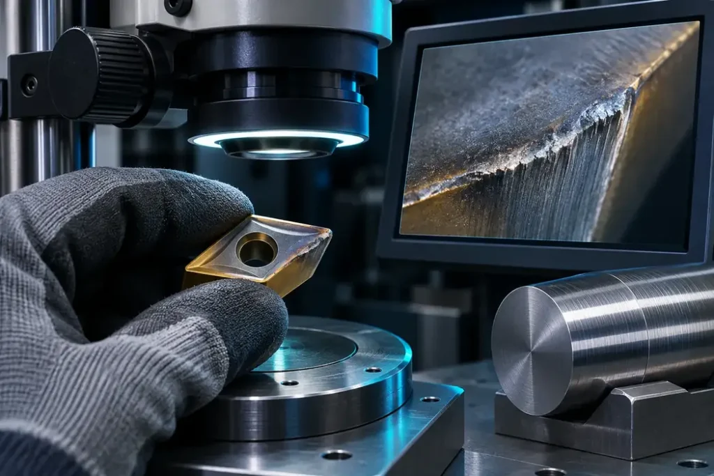
CNC turning chatter: a 7-step troubleshooting checklist. This checklist separates workholding, tool overhang, insert geometry and process evidence when investigating turning chatter.
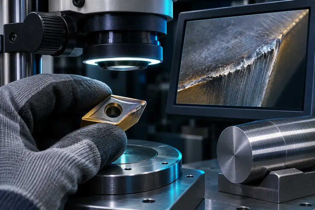
Record safety and onset
Note whether chatter began after an insert change, material change, machine service or program edit. Record time, location and operation stage. Stop the machine under its safety procedure if there is unusual impact or risk of breakage.
Do not approach a rotating spindle or handle chips. Once the machine is stopped and secured, photograph the surface, edge and workholding; visual evidence is a clue, not a diagnosis.
Check workholding and fixture
Compare chuck contact, support and part overhang with the machine maker’s instructions. Incomplete contact or unnecessary free length can affect stability. Only authorized staff should adjust chuck jaws.
If the pattern appears only at one diameter or length, mark that area on the drawing. Include part material and workholding in the report.
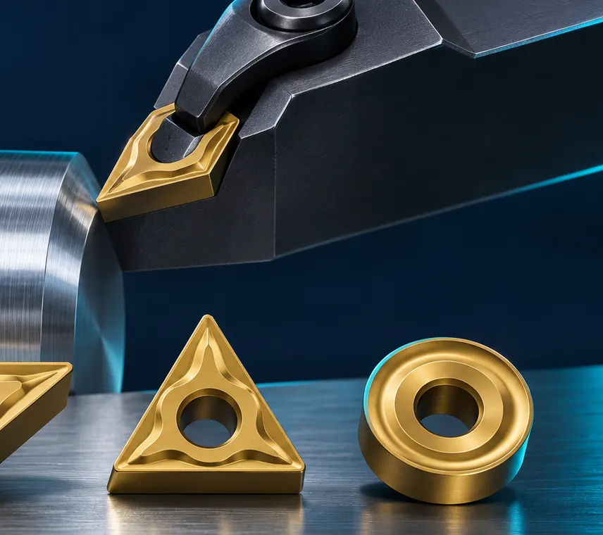
Measure holder overhang
Measure tool overhang and, for boring, the length-to-diameter ratio. Compare them with the holder maker’s recommendations. Longer reach can increase flexibility; use the exact model’s limit.
Inspect turret clamping and the holder seat using approved procedures. For damped tools, stay inside the marked length range. Changes to tool direction or setup need process and safety approval.
Inspect the insert seat and edge
After stopping the machine, check the seat, clamp and insert for chips, burrs or damage. Match the insert code, nose radius and grade to the operation. A chipped edge can affect finish but does not by itself prove the cause of chatter.
Use the maker’s specified clamping method and torque. Record the worn-edge direction and compare it with an unused edge. Review any fracture before restarting.
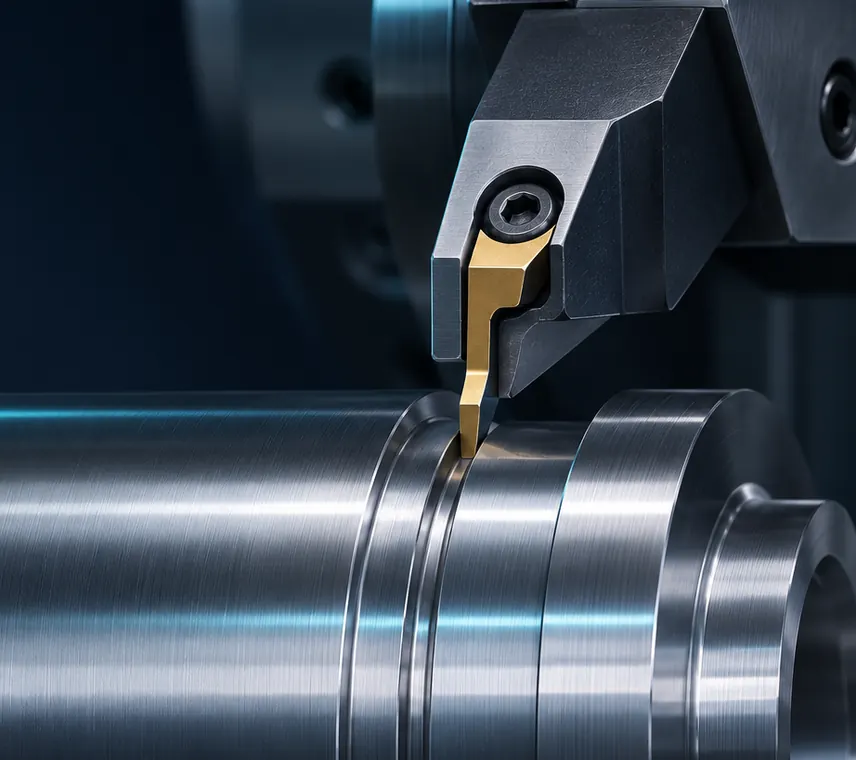
Review cutting data one variable at a time
Read speed, feed, depth, path and coolant conditions from the approved program. Compare them with maker data for the exact grade and material. Do not copy generic values from another part or machine.
Only change one approved factor at a time and record its effect on finish, dimensions and edge condition. Several simultaneous changes make diagnosis unreliable.
Prepare a troubleshooting enquiry
Collect machine, holder and insert codes, material, overhang, onset and defect location. List previous changes and their results. Specific evidence is more useful than a general “machine vibrates” report.
Compare the nose-radius and insert-selection guides, then send the codes and safe photos through the CNC enquiry form.
Separate where and when chatter begins
Record the drawing revision, material condition, raw dimensions, operation sequence, holder code and acceptance criteria. Mark unknown data clearly instead of guessing. A documented selection can be reviewed and repeated when the insert is reordered.
Review workholding by the machine manual
Match the code on the package, maker catalogue and installed holder. Confirm shape, size, thickness, angle, nose radius and grade. Similar appearance or a similar code does not establish compatibility across brands.
Measure tool overhang and connection
Record current tool life, quality and approved conditions before a trial. Change one approved factor at a time, use a representative part and retain a safe return to the verified setup. A single sample does not guarantee production tool life.
Inspect the insert edge and geometry
Check workholding, overhang, turret fit, insert seat and chip clearance under the machine’s safe procedure. These conditions can affect results alongside the insert. Follow the specific machine manual for setup and clamping.
Relate sound, wear and surface evidence
Send the complete holder and insert code, material, operation, quantity, drawing dimensions and quality criterion. Confirm origin, documentation, stock, price and lead time for the exact model before ordering.
Prepare a chatter troubleshooting report
Compare the exact insert code and grade with the maker’s chart for the material, operation, depth and feed. Do not treat a generic finishing or roughing label as a substitute for the documented application range.
Build a traceable case file
Record drawing revision, material, dimensions, operation sequence, holder and insert codes, acceptance criteria and current tool life. Label unknown data instead of guessing. A documented file makes the selection reviewable and helps prevent ordering a tool for an outdated part revision.
Separate an initial suggestion from approval
A preliminary option is not final compatibility approval. Verify the complete code, dimensions, grade, work material and setup with maker documentation and the process owner before use.
Keep purchase and receipt connected
Confirm the exact code, quantity, price, tax and delivery date in a dated quotation. On receipt, compare packaging and product codes with the order and resolve any mismatch before use.
Additional application checks
Describe when and where chatter begins
Record whether the vibration appears on entry, throughout a cut, or only at a particular location. Note the affected surface, operation, material, part dimensions and the time the symptom began. Do not approach rotating equipment to collect evidence; follow workplace safety and quality procedures.
Review the workholding and tool connection safely
Have an authorized operator review the fixture, free length, support, tool overhang, seat and clamping according to the machine manual. Do not guess clamping pressure or alter a live setup. Similar insert codes do not prove that the complete holder and machine arrangement are equally rigid.
Link edge condition to surface and measurements
After safe shutdown, document the insert edge and any wear or damage using an approved method. Relate the observation to measured dimensions, surface criteria and part count. Sound alone is not a reliable basis for changing speed or feed, and a visual mark alone does not identify the cause.
Keep tests controlled and reversible
Record recent changes to material, fixture, holder, insert, program or service. A change occurring near the symptom is a clue, not proof. With the process owner, define one approved variable to test, the acceptance measure and stop criteria. Keep other conditions fixed so the result can be compared.
Escalate unresolved or unsafe conditions
If the condition persists, a fixture is damaged, the machine has a new abnormal sound, or parts fail criteria, follow the site’s escalation process and consult qualified maintenance or the machine maker. Keep the model, approved program revision, event time and prior actions with the report. Remote observations cannot replace an on-site diagnosis.
Frequently asked questions
Can one insert grade work for every setup?
No. Material, operation, holder, cut continuity and maker data all matter; review the exact code and application.
Does chip shape identify the cause?
No. Chip shape is one observation. Compare material, cutting data, geometry and evacuation before concluding.
What should I include in an enquiry?
Include the complete tool codes, material, operation, drawing or key dimensions, quantity and quality criteria.
Technical references
This guide is general information and does not replace drawings, maker data, safety procedures or approval by the process owner. Confirm the exact model, grade and parameters for the actual part and machine.
Explore the industrial tool catalogue or send an enquiry with your specifications.
Use this guide for initial understanding and comparison. For operating limits, safety and exact settings, follow the manual and datasheet for the specific tool model and your workplace procedures.