
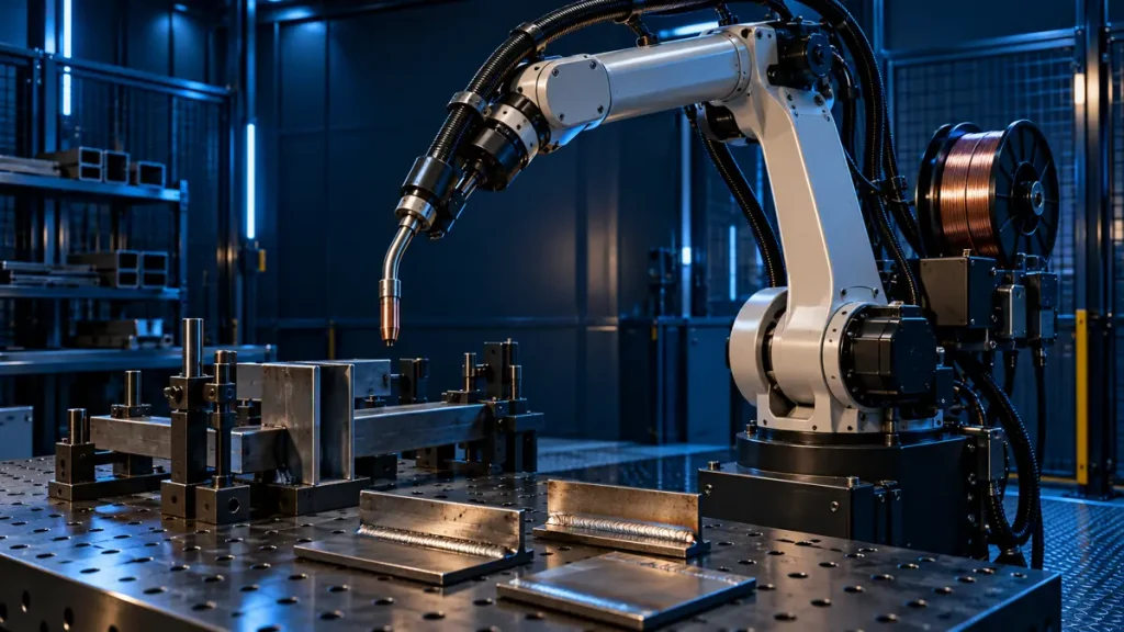
A robotic welding system is more than a robot arm. Results depend on coordination among the robot, torch, welding source, wire feeder, cables, fixture, program and cell guarding. Before comparing models, define the part and joint, then describe the production need in dimensions, process and volume.
Use the process and part as the selection basis
Record the process such as MIG/MAG, TIG or cutting, material and thickness, seam length, joint position, part variation and target cycle time. A sample part and fixture drawing help assess access and torch orientation. A generic “welding robot” label is not enough to define a system.
| Cell area | Information to define |
|---|---|
| Robot | Path, reach, end tooling load and mounting orientation |
| Welding process | Process, power source, torch and wire-feeding method |
| Part handling | Fixture, incoming tolerance and positioner need |
| Controls | Controller, communications, signals and programming tools |
| Safeguarding | Risk assessment, guarding or scanners and safe-stop logic |
Check reach and tooling load against the geometry
Do not rely on the published reach number alone. Simulate the actual path, torch angle, fixture clearance and wrist orientation in the work envelope. Include the mass of torch, cables and end sensors in the tooling load. Confirm each model’s specifications and mounting limits from its own documentation; do not transfer one family’s figures to another model.
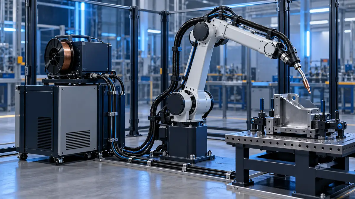
Integrate torch, wire feeder and cable routing
Define the welding-source interface, wire feeder, cable and gas-hose routing, cooling needs and service access in advance. FANUC describes arc welding systems as an integrated combination of robot, welding package, torch, wire feeder and ancillary equipment; review its arc welding robot systems. Compatibility with the selected source and controller must be verified for the exact combination.
Consider fixtures, part repeatability and safety
Describe incoming part variation, locating datums and access for manual or automatic loading. Evaluate positioners, seam sensing or touch sensing from the sample and drawing; not every application needs vision. Safeguarding, emergency stops, operator access and risk assessment should be reviewed against applicable standards, local installation rules and a qualified integrator’s assessment. This guide does not replace a safety assessment or cell design.
Evaluate the welding robot on representative parts
Before finalising a welding robot selection, review one or more representative parts with the proposed fixture. The path should remain accessible throughout, while torch angle, wire entry and exit, nozzle replacement and service access remain acceptable. Do not decide from a model name or nominal reach alone; a path simulation and a trial on a real sample provide more useful evidence.
Define acceptance criteria and result records before a first welding robot trial. The appearance of one pass is not a universal acceptance measure; use the drawing, approved welding procedure and quality-control plan. Record changes to fixture, wire or power source separately so the integration team can trace their effects.
- Identify representative parts and their permitted variation.
- Review path, torch orientation, possible collisions and maintenance access.
- Agree acceptance criteria and the records needed for the trial in advance.
What to send before a project enquiry
- Part drawing and sample, material, thickness and joint photographs.
- Process, existing welding source and torch and feeder specifications.
- Cell dimensions, fixture location, production volume and expected cycle time.
- Electrical, factory-network and maintenance-space limits.
- Safeguarding requirements and existing line equipment to retain.
Frequently asked questions about welding robots
Can the robot arm be bought before selecting welding equipment?
It may be possible, but compatibility among torch, welding source, cables, controller and fixture should be agreed with the integration team before purchase.
How should reach be evaluated?
Simulate the weld path and torch orientation on the actual part and fixture. A reach figure alone is not enough.
For a robotic welding project review, send the part drawing, weld process and existing line information.
Technical references
Practical selection checks
Plan reach along the actual torch path and include tools and cables in the payload review. Check fixtures, extraction, maintenance access and site-specific safeguarding before integration.
Browse the industrial tool catalog or send a technical enquiry.
Additional selection checks
Review torch-tip reach along the real path and include end tooling and cables in the payload check. Fixtures, extraction, maintenance access and site safety need project-specific review.
Browse the industrial tool catalog or send a technical enquiry with the exact code and application.
Use this guide for initial understanding and comparison. For operating limits, safety and exact settings, follow the manual and datasheet for the specific tool model and your workplace procedures.