CNC milling chip evacuation should be planned with the tool and toolpath. Chips left in a slot or pocket may be recut, mark the surface or disturb spindle load. Consider the exit path while defining the feature and cutter.
Slot and pocket geometry
Record slot width, depth, path length and whether the pocket is open or closed. Match cutter diameter, cutting length and overhang to access and holder clearance. A closed slot has limited space for chips to turn and leave. Check machine power, spindle size, coolant availability and workholding.
If the final width exceeds the tool diameter or corner tolerance matters, review the pass count and entry direction in the program and simulation. Cutting forces may deflect the tool or part; do not assume a single-pass strategy is valid for every setup.
Radial and axial engagement
Radial engagement and axial depth affect chip thickness and edge load. Sudden entry, sharp path corners and abrupt direction changes can raise load. Use a gradual or staged entry only within the maker’s and machine’s limits. Describe the operation precisely—slotting, pocketing or side milling—because the generic word “milling” omits useful context.
Chips and coolant
Plan how chips leave before the cutter returns through the path. Coolant through the tool, nozzle direction, air or extraction must follow the maker’s instructions and the workshop’s safety review. Do not direct compressed air at an operator or an open machine area. Dry or wet milling depends on material, tool, machine and maker guidance.
Record sound, spindle load, chip shape, built-up material and surface result. Chip appearance alone does not prove the cause; include material, cutting data and path.
Rigidity and tool choice
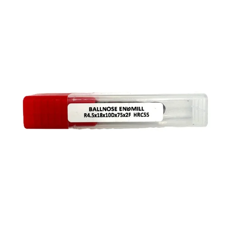
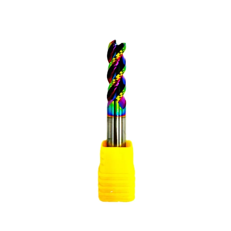
Improving chip flow may require reviewing cutter diameter, cutting length, pass count or toolpath. Changing tools without checking holder and workholding can increase vibration. Confirm code, diameter, flute count and geometry. For example, an AZ end mill listed for aluminum must still be checked against its exact datasheet and operation.
Trial checklist
- Record material condition, drawing revision and slot or pocket dimensions.
- Record tool and holder codes, overhang and coolant setup.
- Keep the source and revision of cutting data and CNC program.
- Change one variable and evaluate chips, surface and machine load.
- Confirm the result and acceptance criteria with the process owner.
Anoush ZAM reports 40 years of machining and technical consulting experience and 2.5 years of sourcing and trade. Send the drawing, workpiece material and model code for an enquiry.
Related catalog examples
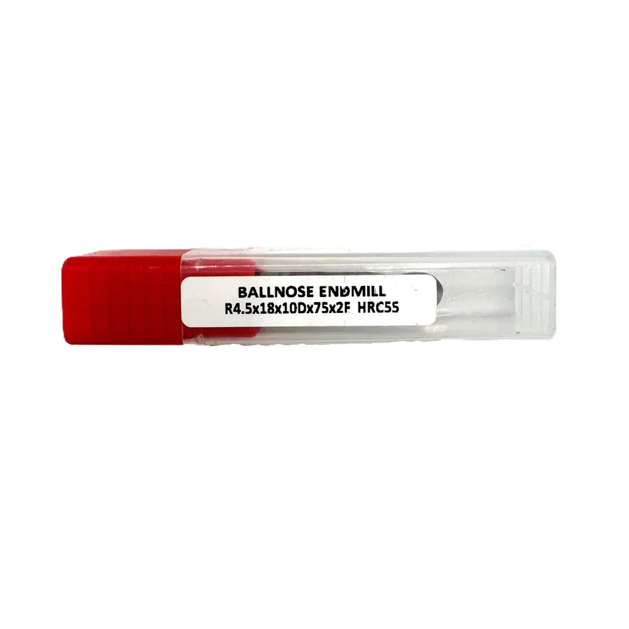
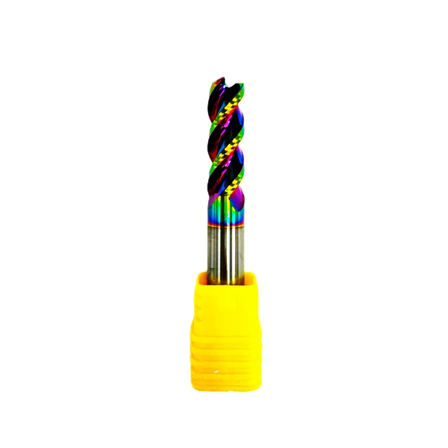
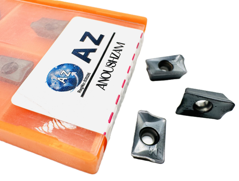
Images illustrate catalog listings. Confirm exact code, fit and availability for your order.
FAQs
What if chips stay in a slot?
Follow the machine’s safe stop procedure, then review evacuation, geometry, coolant and tool-maker guidance.
Will increasing spindle speed solve it?
Not necessarily. Check approved cutting data, engagement, chip exit, material and machine limits first.
Technical references
General guidance only; follow machine safety procedures, exact tool data and the approved program.
Monitor chip evacuation during production
Set an inspection interval that matches the operation risk and machine instructions. Chip buildup, recutting marks, unexpected load or a new sound can justify a safe review. Stop the machine and follow the workshop procedure before approaching the cutting area; never clear chips near moving parts.
Similar pockets can evacuate chips differently because of entry angle, depth and geometry. Check path, nozzle access and compatible coolant equipment before increasing air or fluid pressure. Record a sample chip image and surface result alongside the tool code and program revision to support a repeatable process review.
Use this guide for initial understanding and comparison. For operating limits, safety and exact settings, follow the manual and datasheet for the specific tool model and your workplace procedures.