
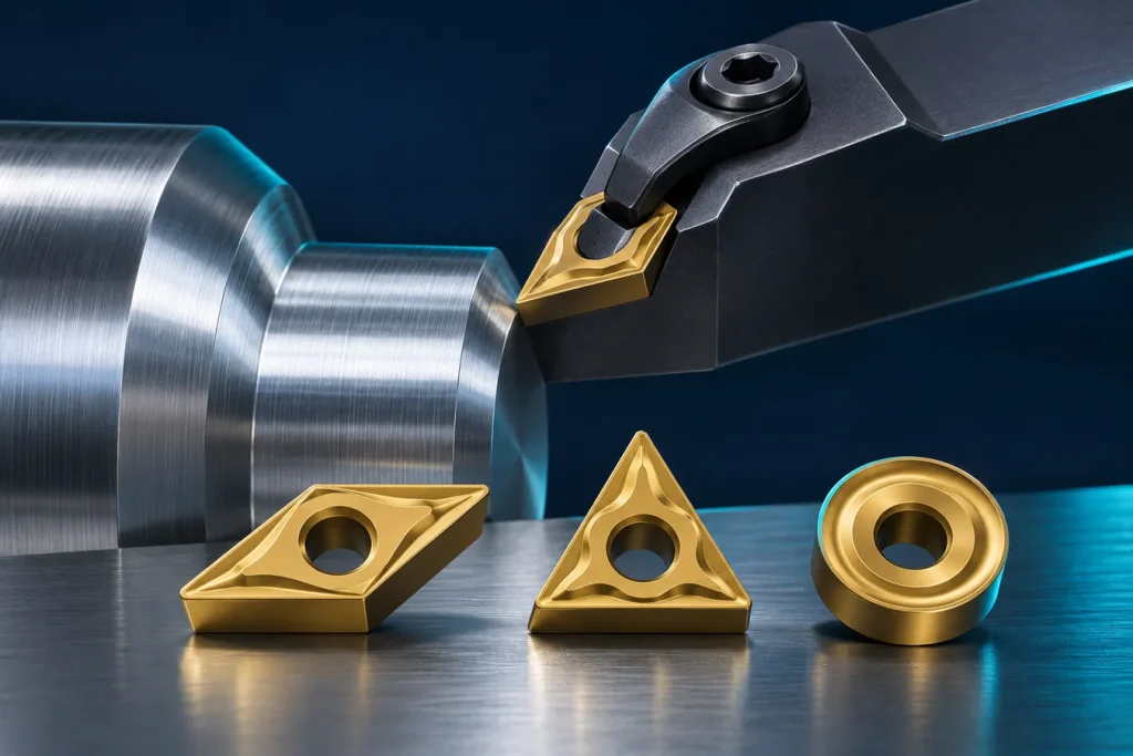
Turning insert geometry affects chip shape, forces and access to the workpiece. Do not stop at triangle or diamond: point angle, entering angle, rake, nose radius and edge preparation also matter. They interact with the operation and system rigidity, so there is no single geometry for every part.
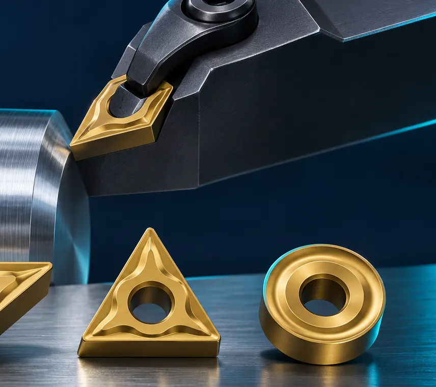
Compare turning insert geometry in one defined cut
To trial turning insert geometry, hold the operation and maker’s permitted range constant. Record the full code, point shape, nose radius, force or unusual sound, surface and edge condition. Then compare one alternative geometry under the same conditions. A better finish alone does not prove a more stable production edge; also compare dimensions, chips and recorded life.
If you know only a brand and the appearance of the turning insert geometry, do not infer a code from a photo. Request the catalogue for that exact model and match shape, size, seat and chipbreaker. Include the complete code and holder photo in an enquiry.
1. Define the operation and target surface
Identify longitudinal turning, facing, profiling, shoulders, chamfers, boring or finishing. Review tool contact on the part drawing and note surfaces that must stay clear. Holder and entering angle are part of selection: a suitable insert may still fail to reach a shoulder or may contact an adjacent feature in the wrong holder.
Record material, real depth and feed, continuous or interrupted conditions and machine rigidity. Maker guidance commonly combines material, operation and machine conditions. If the current setup produces acceptable quality, record its complete tool code as a baseline.
2. Balance positive and negative geometry
A positive rake angle generally reduces cutting forces, while a sharper edge may be less robust. A stronger edge may suit heavier or unstable cuts but can increase force and power demand. Balance workpiece material, edge strength, machine capacity, vibration and surface requirements. Positive or negative alone does not determine quality or fit.
On a less rigid machine or fixture, lower forces and shorter overhang may matter. In interrupted or heavy roughing, a reinforced edge may be a priority. Compare the maker’s geometry chart for the actual application.
3. Match point angle to access and stability
A larger point angle engages more edge and can add strength, but changes access and cutting force. A smaller angle may reach a profile or a corner behind a shoulder, while engaging less edge. Holder entering angle also changes chip thickness and force direction. Review the real path, shoulders, radii and machine capacity on the drawing.
Match insert shape to holder and operation; a profiling insert is not automatically the best choice for longitudinal roughing. Read the full code, tool hand and seat dimensions in the datasheet.
4. Balance nose radius with finish and vibration
A larger nose radius can strengthen the edge and may support a stable surface at a compatible feed and setup, but it also changes radial forces. A smaller radius may be needed for corner access or profiling and can concentrate load near the tip. Do not assume “larger radius means better finish”; operation, feed, depth, vibration and drawing requirements all matter.
If vibration occurs, also check overhang, workholding, centre height and runout. Changing an insert without addressing instability may only change how vibration appears.
5. Choose edge geometry and chipbreaker with the grade
Finishing, medium and roughing geometries can have different edges and chipbreakers. A chipbreaker is designed for a range of feed and depth. Include material and cut continuity; review chip form, surface, evacuation and power limits for the selected series. Choose grade for material and conditions because coatings and substrates differ.
Compare every character of the full insert code with the catalogue. For more on code and chipbreaker, see our CNMG code guide, and for cutting materials see PCD and CBN guidance.
Geometry selection checklist
- Operation and nearby shoulders or profiles.
- Work material and documented hardness.
- Continuous or interrupted cut and system rigidity.
- Holder code, tool hand, entering angle and access.
- Nose radius and surface/tolerance requirement.
- Chipbreaker feed/depth range from the catalogue.
- Machine power, coolant and chip evacuation limits.
FAQs
Is positive geometry always better?
No. Lower force can help, but edge strength and process stability must also suit the actual setup.
Can I choose only from the CNMG shape?
No. The complete code includes more information; grade, chipbreaker, size and application must be confirmed.
Send the drawing and current tool code through our enquiry form to review turning insert geometry. See Sandvik Coromant’s official insert selection guide and turning geometry and force guidance.
General guidance only. Verify geometry and cutting data against the exact insert datasheet, drawing, machine and process owner.
For a fit review of this tool, send the complete code and drawing with your enquiry.
Practical selection checks
Match insert geometry and nose radius to the drawing, toolpath and machine rigidity. Document wear and test one change at a time under the approved process.
Browse the industrial tool catalog or send a technical enquiry.
Additional selection checks
Match insert geometry and nose radius to the drawing, toolpath and machine rigidity. Document wear and test one change at a time under the approved process.
Browse the industrial tool catalog or send a technical enquiry with the exact code and application.
Use this guide for initial understanding and comparison. For operating limits, safety and exact settings, follow the manual and datasheet for the specific tool model and your workplace procedures.