
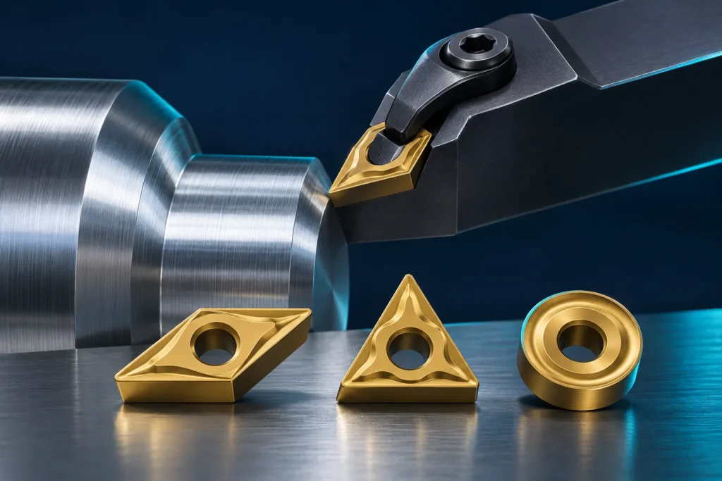
Turning insert nose radius: 6 selection factors. Compare insert nose radius with the drawing, holder, stability and measurable surface criteria before approving a change.
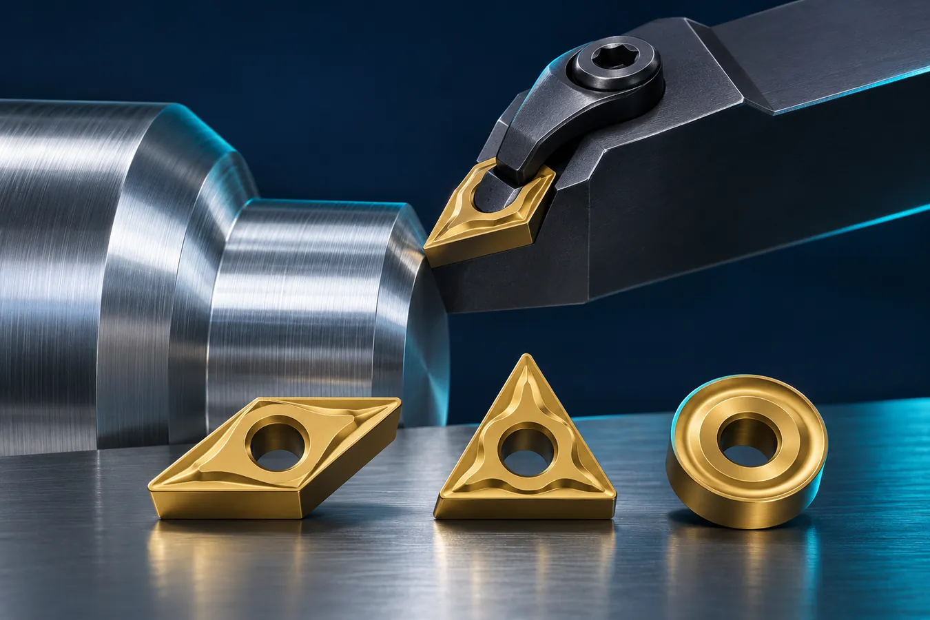
Confirm the code from the package or datasheet
Read the nose-radius designation from the exact maker’s catalog. Code order may differ by series; incomplete codes and appearance alone are not a reliable basis for an order.
If the marking is unreadable, photograph the package and both sides of the insert and ask the supplier to confirm. Shape, thickness, seat and angle must also fit the holder.
Review surface path and cutting load together
Nose radius affects edge engagement and must be considered with feed and entering angle using maker guidance. A theoretical finish table does not guarantee the result on every machine.
A larger radius can provide a stronger edge, while a smaller radius may improve access; stability and cutting force still depend on the actual setup. Treat this as a comparison, not a universal rule.

Check shoulders and tool access
A shoulder, groove, internal radius or contour may not leave enough room for a large nose radius. Check tool and holder clearance against the drawing and approved simulation.
Record entering angle, tool hand and operation. A tool suitable for external turning may not fit an internal or profile cut.
Assess system rigidity before changing the insert
If the surface is wavy or the setup vibrates, first review workholding, overhang, runout and the insert seat. Changing radius without checking basic setup can move the problem rather than solve it.
Record part free length, wall thickness and support with the approved cutting conditions. Ask the process owner to review a tool or fixture change.
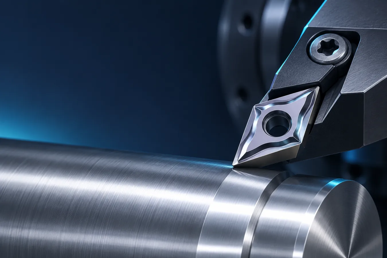
Measure the finished surface consistently
Take tolerance, measurement method and location from the drawing or quality plan. “Good finish” is not a repeatable criterion; the measuring instrument and direction also matter.
Use a representative part and record insert code, radius, grade, holder and approved conditions. Verify several parts under the quality plan; one sample does not guarantee the production lot.
Prepare a nose-radius enquiry
Share the current code, corner drawing, material, operation, holder and surface criterion. If the drawing specifies a radius, quote it exactly and do not assume an unapproved substitution.
Check size, thickness, shape, grade and chipbreaker for the exact model. Review the geometry and wear guides, then send the information in the enquiry form.
Match radius to the drawing and corner
Record the drawing revision, material condition, raw dimensions, operation sequence, holder code and acceptance criteria. Mark unknown data clearly instead of guessing. A documented selection can be reviewed and repeated when the insert is reordered.
Consider the complete insert geometry
Match the code on the package, maker catalogue and installed holder. Confirm shape, size, thickness, angle, nose radius and grade. Similar appearance or a similar code does not establish compatibility across brands.
Define a repeatable surface measurement
Record current tool life, quality and approved conditions before a trial. Change one approved factor at a time, use a representative part and retain a safe return to the verified setup. A single sample does not guarantee production tool life.
Do not attribute every surface defect to radius
Check workholding, overhang, turret fit, insert seat and chip clearance under the machine’s safe procedure. These conditions can affect results alongside the insert. Follow the specific machine manual for setup and clamping.
Provide complete dimensions for a replacement
Send the complete holder and insert code, material, operation, quantity, drawing dimensions and quality criterion. Confirm origin, documentation, stock, price and lead time for the exact model before ordering.
Final nose-radius checklist
Compare the exact insert code and grade with the maker’s chart for the material, operation, depth and feed. Do not treat a generic finishing or roughing label as a substitute for the documented application range.
Build a traceable case file
Record drawing revision, material, dimensions, operation sequence, holder and insert codes, acceptance criteria and current tool life. Label unknown data instead of guessing. A documented file makes the selection reviewable and helps prevent ordering a tool for an outdated part revision.
Separate an initial suggestion from approval
A preliminary option is not final compatibility approval. Verify the complete code, dimensions, grade, work material and setup with maker documentation and the process owner before use.
Keep purchase and receipt connected
Confirm the exact code, quantity, price, tax and delivery date in a dated quotation. On receipt, compare packaging and product codes with the order and resolve any mismatch before use.
Additional application checks
Separate the insert radius from the part corner
Read the insert nose radius from its complete code and catalogue; read the finished part corner and tolerance from the drawing. Record them separately. Similar numerical values do not prove the insert, holder, clearance and part profile will fit the intended operation.
Review the complete geometry and access
Surface and cutting load also depend on insert shape, entry angle, chipbreaker, material, tool path, rigidity and operation. Check shoulders, profiles, boring access and chip clearance against the actual setup. A larger or smaller radius is not a universal remedy for chatter or finish.
Define a repeatable surface measurement
Use the drawing or quality plan for roughness, measurement method, location and sample count. Visual appearance alone is not a numeric result. Compare representative parts under consistent conditions, and record tool code, holder, material and inspection method with the result.
Approve a controlled comparison
If a radius change is considered, document the reason and change one approved factor at a time. Inspect the active edge and seat only after safe shutdown. Do not treat a single part as a production guarantee. Confirm the maker’s dimensional cross-reference before substituting another brand.
Make the replacement enquiry complete
Include the current insert and holder codes, shape, size, thickness, radius, grade, material, operation and quality criterion. State whether the request concerns a drawing corner, surface result or tool access. Confirm compatibility with the process owner before purchase and verify the exact code on receipt.
Frequently asked questions
Can one insert grade work for every setup?
No. Material, operation, holder, cut continuity and maker data all matter; review the exact code and application.
Does chip shape identify the cause?
No. Chip shape is one observation. Compare material, cutting data, geometry and evacuation before concluding.
What should I include in an enquiry?
Include the complete tool codes, material, operation, drawing or key dimensions, quantity and quality criteria.
Technical references
This guide is general information and does not replace drawings, maker data, safety procedures or approval by the process owner. Confirm the exact model, grade and parameters for the actual part and machine.
Explore the industrial tool catalogue or send an enquiry with your specifications.
Use this guide for initial understanding and comparison. For operating limits, safety and exact settings, follow the manual and datasheet for the specific tool model and your workplace procedures.