CNC cutting speed and feed should come from the tool data, workpiece condition and machine capability. A value that fits one material, diameter or operation is not a universal setting. This guide shows how to record the data source and convert it to spindle speed and table feed.
Use the exact tool data
Match tool code and grade, workpiece group, operation, engaged diameter, axial and radial depth and coolant condition to the maker’s table. Record the guide version. Cutting speed (Vc), feed per tooth (fz), effective teeth (zc) and spindle speed (n) are separate values; table feed is not cutting speed.
Machine, holder, overhang, workholding, vibration and finish requirements also matter. If the manufacturer does not publish data for the exact combination, request confirmation from the maker or process engineer.
Milling spindle speed and feed
With cutting diameter D in millimetres and Vc in metres per minute, a common spindle-speed conversion is n = (1000 × Vc) ÷ (π × D). With feed per tooth fz in millimetres and effective teeth zc, table feed is vf = fz × zc × n. Keep units consistent and check the machine’s speed, feed, power and torque limits.
These formulas convert units; they do not recommend a cutting value. Take Vc and fz from approved data for the exact tool and material. Formulas never replace machine limits or safety instructions.
Effective diameter for ball-nose tools
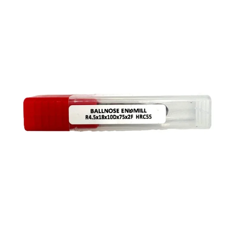
For ball-nose and radius tools, the effective diameter at the contact point may be smaller than the nominal diameter. Using nominal diameter can understate actual edge speed at shallow engagement. Account for cut depth, surface angle and contact point using the manufacturer’s method. Catalog tools such as the AZ ball-nose end mill require the exact code and model table.
One-variable test and logging
- Record material condition, drawing and finish or tolerance target.
- Record tool and holder codes, overhang, engaged diameter and coolant.
- Record the source of Vc and fz and the CNC program revision.
- Change one factor and inspect load, sound, chips, wear and surface.
- Confirm stop and acceptance criteria with the process owner.
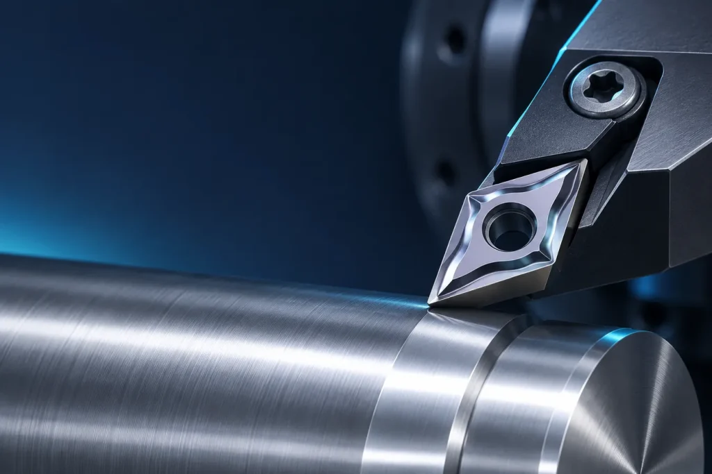
Changing several values at once obscures the cause. Turning has its own data relationships for speed, feed per revolution and depth; do not substitute milling recommendations for turning data.
Anoush ZAM catalog and technical review
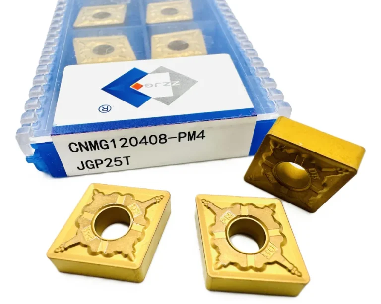
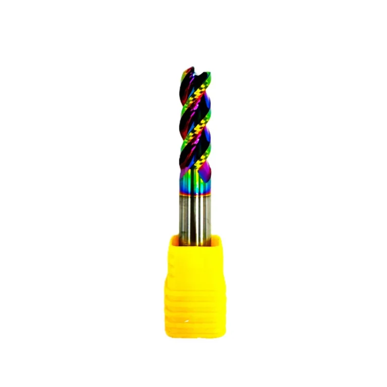
The Anoush ZAM catalog includes tools such as a ZZJG CNMG120408-PM4 JGP25T turning insert and milling tools. This guide does not guarantee a cutting parameter or outcome for every application; model, origin, documents, availability and supply terms must be checked for each order. Anoush ZAM reports 40 years of machining and technical consulting experience and 2.5 years in sourcing and trade.
For technical review, share the tool code, workpiece material, engagement, operation and machine model in an enquiry.
Related catalog examples
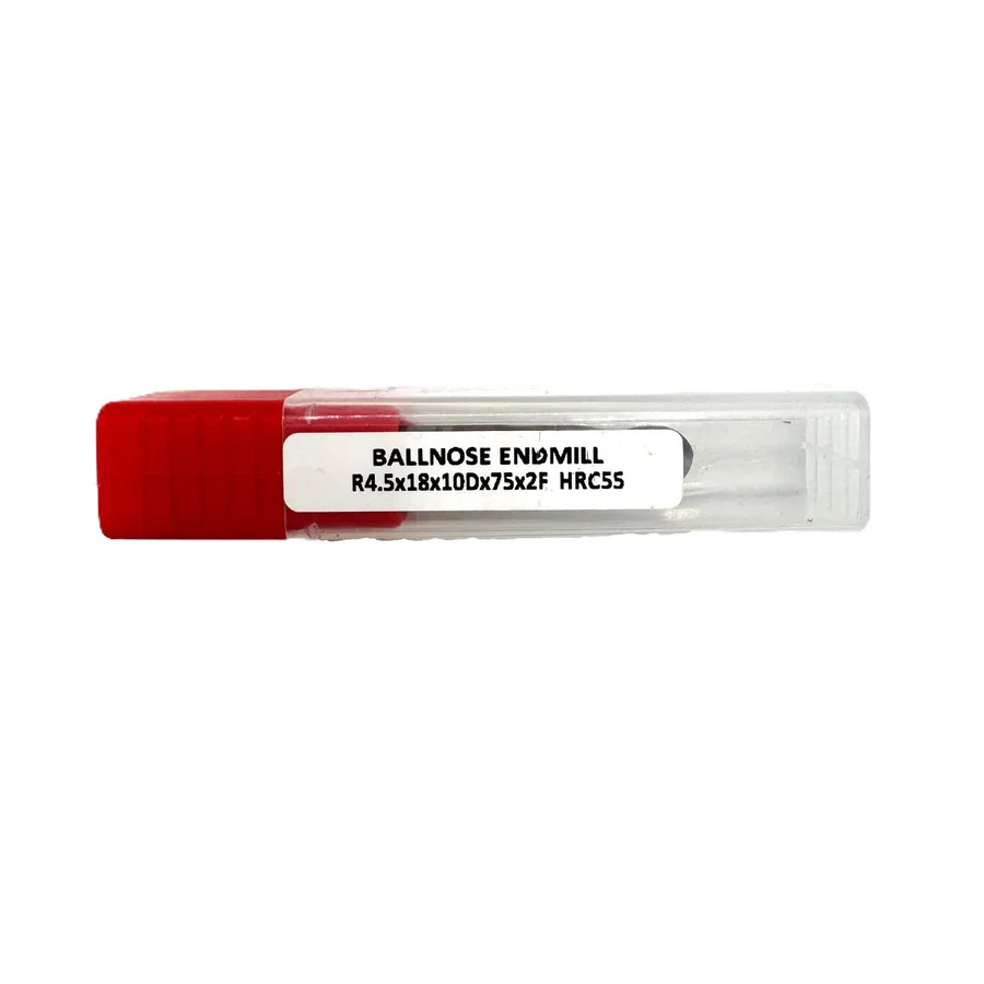
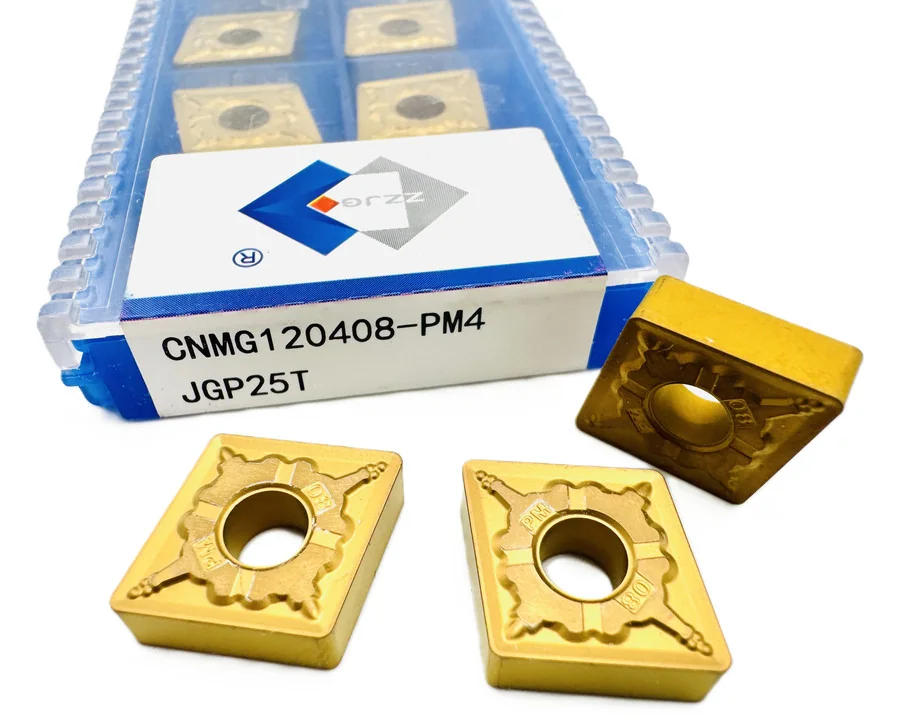
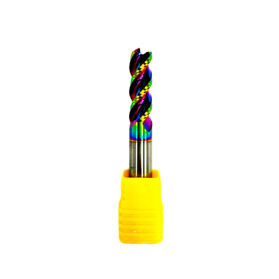
Images illustrate catalog listings. Confirm exact code, fit and availability for your order.
FAQs
Are spindle speed and cutting speed the same?
No. Vc is the linear speed at the cutting edge; n is spindle revolutions. Diameter is needed to convert them.
Can I use a data-table value from another brand?
Only if the maker and process owner confirm compatibility; similar geometry or grade labels are not enough.
Technical references
- Milling speed and feed formulas — Sandvik Coromant
- Effective ball-nose diameter — Sandvik Coromant
- Turning speed, feed and depth — Sandvik Coromant
Use exact tool data, an approved program and workshop safety procedures for machining parameters.
Common speed and feed conversion errors
Confusing metres per minute with millimetres per minute or using the wrong cutting diameter changes the result. Another error is entering the nominal tooth count when fewer teeth are effectively engaged. Check the machine’s spindle and axis limits, power, torque, holder and workholding before running a calculated value.
With ball-nose and radius tools, contact location depends on depth and surface angle, so nominal diameter may not represent the engaged edge. Store the units, data source and datasheet revision with each calculation. A process owner should define the safe range and stop criteria. That record makes future settings reviewable instead of transferring one unsupported number between different tools and parts.
Use this guide for initial understanding and comparison. For operating limits, safety and exact settings, follow the manual and datasheet for the specific tool model and your workplace procedures.