
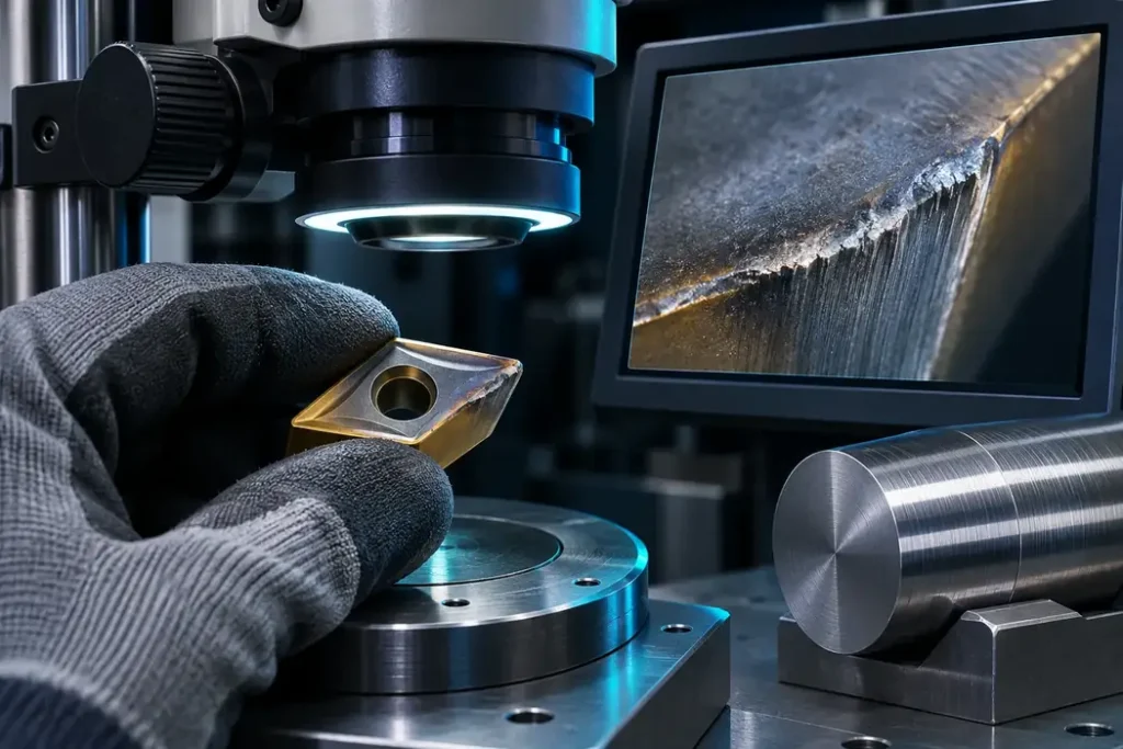
When tool life falls, changing grade immediately may not solve the problem. Turning insert wear should be reviewed with wear location, chip form, part surface and machine setup. One sign can have multiple causes, so this guide offers a recording and trial method rather than a diagnosis from one photo.
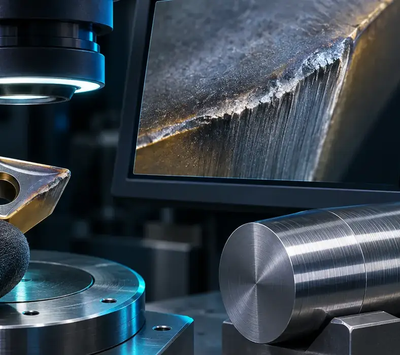
Record a wear pattern for insert troubleshooting
When reviewing turning insert wear, keep each used edge with cutting time and part count so samples can be compared. Photograph from a consistent angle and mark the contact region and depth-of-cut line. If vibration or surface changes appear alongside wear, also record clamping, overhang and runout. Treat these as observations; do not state a cause as certain until a test supports it.
Choose a similar part and the same quality criterion for comparison. If turning insert wear improves after a tool change, keep trial conditions, removal volume and stop criterion with the result. A clear record helps the team avoid applying experience from a different machine or material.
1. Record evidence before changing the tool
Note the full insert and grade code, work material, operation, parts or cutting time, approved program data, coolant state and workholding. Photograph the edge, clearance face, rake face and machined surface. Mark the wear position: near the tip, along the edge, at depth-of-cut line or on the rake face. Direction and scale matter; if possible record an unused and worn insert together.
Compare tool-change interval against the part’s quality or defined wear limit. Tool-life comparisons are meaningful only when material, removal volume, tolerance and machine conditions are comparable.
2. Distinguish flank, notch and crater patterns
Flank wear appears on the clearance face and may relate to time or thermal conditions, but it does not identify a single cause. Notching at the depth-of-cut line may relate to scale, surface hardness or workpiece conditions. Cratering on the rake face must be reviewed with grade, speed and material. Change speed or grade only after checking maker data and recording the baseline.
Inspect the part as well. A poor finish, dimensional change or marks may be associated with wear, runout, vibration or trapped chips. Use the approved measurement method and isolate questionable parts according to the quality procedure.
3. Inspect chipping and edge fracture
Small chips or sudden fracture can relate to entry and exit impacts, poor clamping, an edge too fragile for the operation, vibration or tool collision. Confirm holes and slots on the drawing where the cut is interrupted. Check seat cleanliness, screw, shim and clamping as specified; a loose assembly can repeat the issue.
Before selecting a stronger edge, confirm current geometry, holder and program path. A tougher grade does not replace correcting collisions, excessive overhang or unstable workholding. Coordinate changes with the machine and process owner.
4. Interpret built-up material and surface carefully
Material adhered to the edge or poor finish may indicate an interaction of material, geometry, thermal condition and chipbreaker, but does not prove one cause. Inspect the tool and part only after stopping and securing the machine. Check coolant delivery, continuity, chipbreaker and approved feed range against the maker’s instructions. For work-hardening materials, discuss path or depth changes with the process owner.
Never remove long chips by hand from a running machine. Use the shop’s approved stop and removal method and follow its safety procedure for cleanup.
5. Design a controlled trial
Define the issue first: early fracture, poor finish, dimensional drift or inconsistent chips. Form one testable hypothesis and change one factor within allowed limits, such as correcting the seat or testing a grade recommended for the material and operation. Record part, tool and machine time as a sample. Compare quality and wear at a fixed point.
If a new tool appears better, verify representative parts under the quality plan. One successful sample does not prove guaranteed tool life or the same result for an entire production run. Record acceptance criteria and trial conditions internally.
Troubleshooting checklist
- Edge photos with clear direction and scale.
- Complete insert, holder and grade code.
- Work material, drawing and cut continuity.
- Program data and coolant condition.
- Cutting time or part count and previous stop reason.
- Part dimensions, finish and acceptance criterion.
- Recent machine, fixture or material changes.
FAQs
Will changing grade always extend insert life?
No. If vibration, poor clamping or trapped chips are present, a grade change may leave the root cause. Check baseline conditions and compare trials carefully.
Should I change several factors at once?
For troubleshooting, change one defined factor at a time so its effect can be separated; keep every change within the maker’s permitted data.
Send the tool code, material and worn-edge photo through our technical enquiry form for an evidence-based review of turning insert wear. Sandvik’s guide to wear, built-up edge and threading conditions discusses how cutting conditions affect the process; its turning and wear guidance provides further context.
Final diagnosis depends on examining the actual tool, part and machine. This guide does not replace maker instructions, shop safety or process approval.
For a fit review of this tool, send the complete code and drawing with your enquiry.
Practical selection checks
Photograph the clean edge from multiple angles and record material, insert code, operation and chip shape. Treat wear signs as clues, then test one corrective action at a time.
Browse the industrial tool catalog or send a technical enquiry.
Additional selection checks
Photograph the clean edge from multiple angles and record the material, insert code, operation and chip shape. Treat wear signs as clues, then test one corrective action at a time.
Browse the industrial tool catalog or send a technical enquiry with the exact code and application.
Use this guide for initial understanding and comparison. For operating limits, safety and exact settings, follow the manual and datasheet for the specific tool model and your workplace procedures.