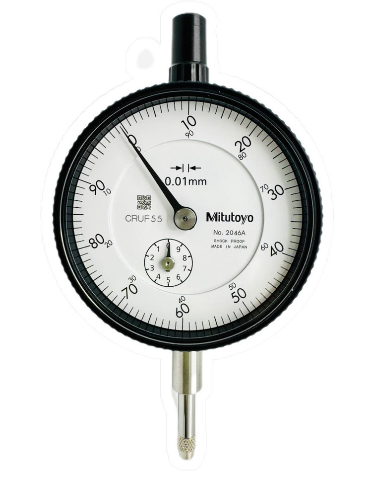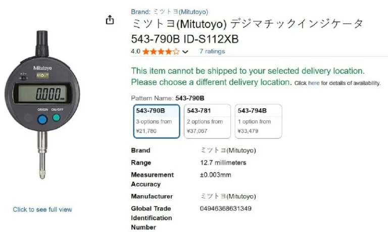
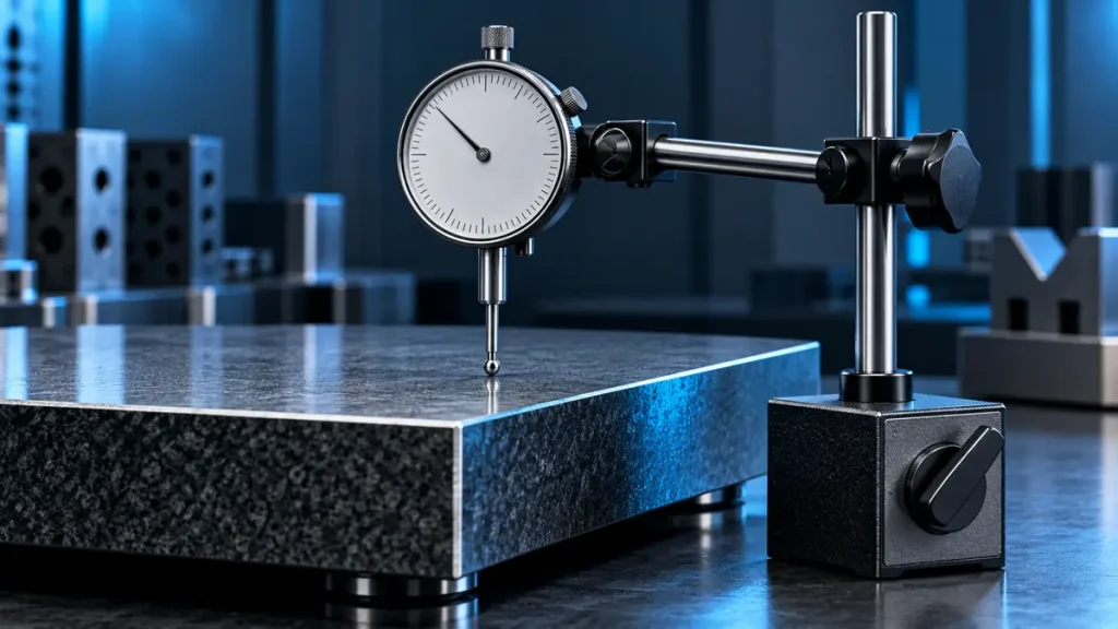
A dial indicator can help inspect small changes, alignment and runout, but choosing the dial face alone is not enough. Range, resolution, contact style, movement angle and the support holding the instrument must all suit the measurement method.
Match range and resolution to the measurement
Estimate the expected movement and compare it with the instrument’s full range. A smaller resolution by itself does not prove better accuracy; read the model data for permissible error, repeatability, measuring force and mounting conditions too. Mitutoyo lists separate families for dial indicators and dial test indicators; review the maker’s indicator range.
| Application | Specification to check |
|---|---|
| Linear movement | Range, resolution and travel |
| Alignment or runout | Contact type, access and stylus angle |
| Machine mounting | Compatible stem diameter or dovetail connection |
| Recording results | Dial readability or required data output |
Dial indicator or dial test indicator?
A plunger-style indicator is designed for contact along its spindle travel; a lever-type instrument provides different access and is more sensitive to probe direction. With a lever-type indicator, keep the angle between workpiece movement and stylus movement small, or apply the cosine effect as stated by the maker. Mitutoyo notes that the scale factor depends on this angle. It also advises using a fixture that does not deflect significantly in normal use; see its measuring-instrument check points.
The magnetic stand is part of the measurement chain
Match the indicator stem diameter and dovetail connection to the stand clamp. Check arm reach, joints, mechanical locking and fine adjustment against the available space. A long arm or loose joint can shift during contact; secure the joints and check assembly stability before zeroing. Mitutoyo’s magnetic stand range lists different sizes and locking arrangements, which should not be assumed to be identical across models.
Keep setup and reading method consistent
- Clean the mounting surface and contact point; check the stylus for damage.
- Place the base near the measurement point on a stable surface.
- Position the stylus within its permitted working travel and in a suitable direction.
- Move the part repeatedly using the same method and record pointer return.
- Compare the required result with drawing tolerance and instrument calibration status.
What to include in an indicator enquiry
Specify required range and resolution, plunger or lever type, connection form, mounting space, stand type, data output and any calibration documentation. If you already have an instrument, include a photograph of its model code and connection. Browse the measuring tools catalog or request a dial indicator quotation.
Frequently asked questions about dial indicators
Can a stronger stand compensate for indicator error?
No. A stable stand reduces unwanted movement of the fixture; instrument characteristics, contact method and calibration remain separate considerations.
Can a lever indicator be read at any angle?
No. The angle affects the scale factor. Follow the maker’s method and, where practical, align the stylus close to the workpiece direction.
Technical references
Practical selection checks
Match range and graduation to the measurement. Use a short rigid arm, align the contact point with movement and repeat the approach. State the mounting interface and calibration needs.
Browse the industrial tool catalog or send a technical enquiry.
Additional selection checks
Select range and graduation for the measurement. Mount the indicator rigidly, align its contact with the movement and repeat the approach. Record the mounting and calibration requirements.
Browse the industrial tool catalog or send a technical enquiry with the exact code and application.
Use this guide for initial understanding and comparison. For operating limits, safety and exact settings, follow the manual and datasheet for the specific tool model and your workplace procedures.