
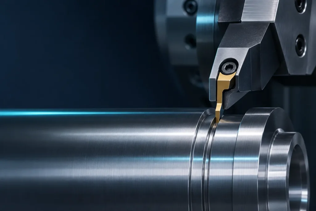
A grooving insert must suit the groove shape, tool access and chip exit. A narrow deep groove, face groove and internal groove have different constraints. Turn the drawing into dimensions and application questions before ordering; nominal insert width alone may not match the holder or programmed path.
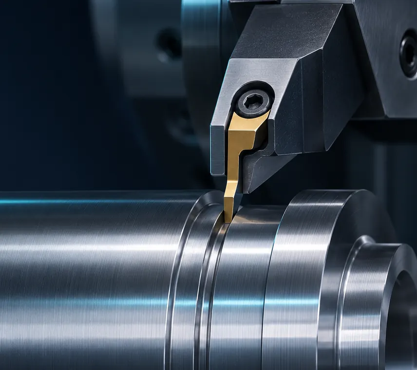
Trial a grooving insert on a representative part
For a grooving insert, inspect a sample for width, depth and groove position. Record chip exit and any effect on the floor or wall. If width is outside tolerance, check whether the insert has clearance through the full depth or the holder contacts a shoulder. Do not change the programmed width without confirming the path and tool code.
Include the groove section drawing, diameter and operation direction in a grooving insert enquiry. For internal or face grooving, a side view or path image helps confirm access. These details support a better fit and reduce reliance on nominal insert width alone.
1. Record geometry from the drawing
Capture width, depth, start and end diameters, corner radius and nearby shoulders. For face grooving, path radius and diameter range matter; for internal grooving, minimum bore and distance to the groove floor limit tool entry and exit. If width has a tolerance, state whether one insert must generate the full width or whether side movement and a finishing pass are planned.
Check edge geometry and nose radius against the system catalogue. A narrower tool may provide more clearance but less stiffness; a wider tool may not pass a shoulder. Choose from actual part and holder dimensions, not from a product photo.
2. Define groove type and cutting path
The operation may be external, face, internal grooving or parting. In face grooving, the holder must support the curved path, and curve direction, tool hand and diameter range must suit workpiece rotation. For parting, control of the released part, exit path and support are also process-safety issues; this is more than choosing a blade.
Match groove floor, radius and corners to the insert profile. Send the drawing and pass sequence for special profiles or multi-stage grooves. A simple ring groove may start with a straight plunge, while face or profiled grooves can need combined movements.
3. Check holder rigidity and access
Keep overhang as short as the setup permits, match shank and turret interface, and inspect clamping. In deep grooving, force and vibration risk may increase. Face grooving needs a holder suitable for the path diameter and direction. For boring, include surrounding clearance and bar overhang ratio.
Review machine condition, workholding and coolant access before final selection. Record the exact current holder and insert code; similar dimensions do not guarantee the same seat or clamp.
4. Manage chips in the narrow path
Chips trapped in a groove can scratch the surface or damage the edge. Match chipbreaker, feed and depth to the maker’s range. Check chip exit and coolant access. In face grooving, chips can get caught in the curved path; consult the maker’s recommendations for infeed, brief pauses or staged cuts for that tool.
If vibration or unusual noise occurs, stop safely and check workholding, tool overhang, seat and chips. Changing data without finding the cause may worsen the condition. Do not copy speed and feed from an unrelated tool or material.
5. Define measurement and trial
Before ordering, decide how width and depth will be measured and which datum controls the dimensions. Compare corner radius and groove position with the drawing. For an important first article, record a trial part and surface acceptance criterion. Photograph the used edge from two views and note change interval or parts completed.
Our insert-code and chipbreaker guide covers basic markings. Browse available CNC tools and inserts, then confirm size and holder fit before ordering.
Enquiry checklist
- Groove drawing with width, depth, radius and start/end diameters.
- External, face, internal or parting operation.
- Holder code, machine interface, overhang and clamping.
- Work material and continuous or interrupted conditions.
- Measurement method and required tolerance.
- Chip and worn-insert photos, if available.
FAQs
Must the insert width equal the groove width?
It depends on tolerance, corner radius, path and machining strategy. Nominal width alone is not enough; verify with the holder catalogue and drawing.
Why can chips get stuck in a face groove?
The curved path and limited exit space can make evacuation difficult. Check the path, chipbreaker, tool and coolant against guidance for the specific system.
Send the drawing and holder code through our enquiry form to review a grooving insert. Sandvik Coromant’s official face-grooving guide covers radius, depth and tool stiffness considerations.
General guidance only. Verify the drawing, tool maker’s instructions, machine and shop safety requirements before machining.
For a fit review of this tool, send the complete code and drawing with your enquiry.
Practical selection checks
Record groove width, depth, shoulder clearance and tool access. Confirm holder reach and chip evacuation, then check width and depth using the approved method.
Browse the industrial tool catalog or send a technical enquiry.
Additional selection checks
Record groove width, depth, shoulder clearance and tool access. Confirm holder reach and chip evacuation, then check dimensions with the approved measurement method.
Browse the industrial tool catalog or send a technical enquiry with the exact code and application.
Use this guide for initial understanding and comparison. For operating limits, safety and exact settings, follow the manual and datasheet for the specific tool model and your workplace procedures.