

When selecting a threading insert, the tip shape alone is not enough. Thread standard, pitch or TPI, diameter, hand, internal/external application and machine limits must match the insert and holder. This guide lists the information to gather before an enquiry; do not infer thread dimensions from appearance.
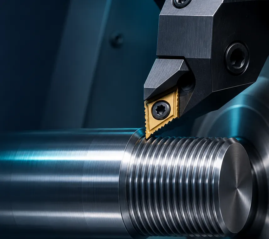
Verify the first part with a threading insert
After fitting a threading insert, make a sample using the approved cycle and inspect it with the gauge and method specified on the drawing. Record the result with pitch, diameter and hand; for internal threads, consider gauge access and usable depth too. Replace a full-profile insert with a V-profile type only when profile, pitch and nose radius are compatible according to the maker.
If chips do not leave the cut cleanly, review the program, infeed direction and exit path with the process owner. Choosing a threading insert without the thread standard and pitch can create a nonconforming thread even when the nominal dimensions look close. Check the drawing and tool code together before ordering.
1. Define the thread from the drawing
Record the thread designation, nominal diameter, pitch or TPI, tolerance class, engagement length and hand. Metric, inch, pipe, trapezoidal and proprietary forms do not share the same requirements. If only a diameter is shown, ask the designer or maintenance team to confirm the profile and pitch. For internal threads, the pre-bore diameter and usable depth also affect insert access and chip removal.
Check right- or left-hand direction against spindle rotation, tool approach and exit clearance. Chamfers, shoulders and relief space may constrain the holder or machine cycle. A sample fastener can help an initial check but does not replace the drawing and thread standard.
2. Match the threading insert type to the job
A full-profile insert forms a defined thread profile and generally requires a matching type for each pitch and standard; follow guidance for the finished diameter. A V-profile insert can cover a pitch range only when its profile angle and nose radius are suitable, and it may not finish the crest. A multi-point type can reduce passes in a suitable setup, but check contact length, exit space and machine stability before selecting it.
For 55- or 60-degree, trapezoidal and pipe forms, match the exact code and profile to the drawing and catalogue. The wrong included angle can produce a nonconforming thread even when the nominal diameter is correct. Compare the full insert code and pitch marking before ordering.
3. Confirm flank clearance and shim
The insert needs clearance as it follows the thread helix. Inclination and shim choice depend on diameter, pitch or lead, thread type and holder. A holder may include a standard shim, but that does not prove it suits every thread. Follow the maker’s method for the actual thread, especially for left-hand threads, coarse pitches and non-metric forms. Do not transfer a catalogue example to a different diameter or pitch without checking.
After fitting, check that the insert seats fully and that edge direction and overhang are correct. A damaged shim or uncertain fit can affect flank quality and edge life. Make adjustments only with the spindle safely stopped and suitable measuring tools.
4. Select internal and external tooling separately
For internal threading, bore space, bar length-to-diameter ratio, minimum bore and end access matter. The tool must reach the thread end while leaving chips a way out. External threading may be constrained by shoulders, exit clearance and holder orientation. Match the holder to shank size, turret interface, clamping method and insert code; brand name alone does not establish compatibility.
5. Monitor chips and the threading cycle
Long chips can scratch a surface or interrupt production. Review evacuation, coolant and infeed method for the material and machine cycle. A maker may recommend modified flank infeed or another path; the correct choice depends on the thread and setup. Take pass count, speed and feed from the selected grade’s data, then verify the first part with an appropriate inspection method.
Check thread gauge, diameter and pitch against the drawing and quality plan. If the profile is incomplete, confirm the insert standard, pitch, radius and direction before changing offsets. Record passes and corrections so the result is repeatable.
Enquiry checklist
- Thread standard/designation, diameter and pitch/TPI.
- Internal/external, right/left hand, length and form.
- Current holder and insert code, seat size and shim.
- Pre-bore diameter and access limits for internal threads.
- Workpiece material and documented hardness, if available.
- Controller or threading cycle and inspection method.
FAQs
Does a V-profile insert suit every pitch?
No. Its usable range depends on the maker’s profile angle and nose-radius specification, and the thread crest may need finishing.
Can I always keep the holder’s supplied shim?
Not automatically. Confirm insert inclination and flank clearance for the thread, diameter, pitch and holder instructions.
Send a drawing image and holder code through our enquiry form to review a threading insert. See the official Sandvik insert and shim guide and threading application tips.
This is general guidance. Verify dimensions, thread type and cycle settings against the drawing, manufacturer catalogue and part inspection plan.
For a fit review of this tool, send the complete code and drawing with your enquiry.
Practical selection checks
Specify thread standard, profile, pitch, diameter and internal or external use from the drawing. Verify the result with the approved gauge; do not infer the standard from appearance.
Browse the industrial tool catalog or send a technical enquiry.
Additional selection checks
Specify the thread standard, profile, pitch, diameter and internal or external use from the drawing. Verify the result with the approved gauge; do not infer the standard from appearance.
Browse the industrial tool catalog or send a technical enquiry with the exact code and application.
Use this guide for initial understanding and comparison. For operating limits, safety and exact settings, follow the manual and datasheet for the specific tool model and your workplace procedures.