
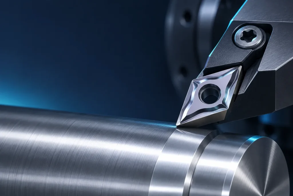
A stainless steel turning insert cannot be selected reliably by appearance or grade name alone. Stainless materials differ in structure, work hardening, chip adhesion and surface condition. This guide provides a practical pre-order checklist. Cutting speed and feed are not universal; use the manufacturer’s data for the exact insert grade and workpiece.
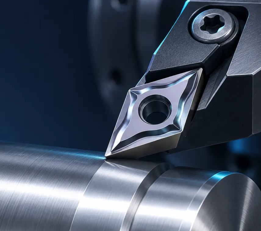
Trial planning for stainless steel inserts
Choose one representative part and an acceptance criterion before comparing options. Record the stainless steel insert code and grade, part count, cutting time, surface result and chip form. Then test one option inside the manufacturer’s range. If the finish improves but the edge fails earlier, evaluate those outcomes separately; one measure does not describe the entire process.
In a sourcing enquiry, include the material number with the stainless steel insert application so code, geometry and grade can be reviewed together. If the work material is uncertain, state that and obtain confirmation before ordering. This avoids relying on a short product title and makes later comparison more repeatable.
1. Identify the work material first
“Stainless steel” is not a complete material specification. Record the material number or standard on the drawing, heat-treated condition, documented hardness and raw surface condition. Austenitic, ferritic, martensitic and duplex grades can behave differently; appearance alone is not a reliable identifier. If the material number is missing, ask the part supplier or process owner to confirm it.
Many stainless grades are grouped under ISO M in common cutting-tool classifications, but that label does not specify a grade or cutting data. Check the material subgroup, hardness, cut continuity and machine rigidity together in the selected manufacturer’s application table. Sandvik’s selection guidance likewise considers workpiece material, operation and machine conditions; a family label alone is not enough to order.
2. Do not treat finishing and roughing as the same cut
Record depth of cut, feed, stock allowance and whether the path is continuous or interrupted. A sharp finishing geometry is designed for light cuts; a stronger edge may suit heavier loads. Swapping them can lead to poor chip control, edge chipping or a poor surface. The chipbreaker must also operate inside its stated feed and depth range.
Report scale, cross-holes, slots and interrupted sections. Entry and exit impacts can damage a weaker edge. If the part, fixture or machine vibrates, first inspect tool overhang, workholding, runout and the insert seat before changing grade.
3. Treat geometry, grade and chipbreaker as a system
Edge geometry influences cutting forces and chip form. Grade substrate and coating are designed for particular material and heat combinations, so the “hardest” grade is not automatically the right one. A sharper geometry may reduce forces in a sticky material, while edge strength may matter more in unstable cutting. These are selection directions, not a substitute for the exact grade chart and part specification.
Do not ignore long or tangled chips. Match the chipbreaker range to actual feed and depth, and check chip evacuation and coolant access in internal operations. Do not copy a speed or feed from an unrelated online example. Take the starting range from the selected manufacturer’s data and confirm it with a controlled trial.
4. Check the holder, clamping and coolant
Match the insert code, size, shape, thickness and seat to the holder. A clean seat, sound screw or clamp, tightening as specified, and short overhang support stability. For boring, bar overhang and chip clearance deserve extra attention. If the holder or tool hand changes, verify the tool direction and spindle rotation against the machine program.
Change coolant type or pressure only in line with maker guidance and available equipment. Intermittent coolant can create thermal shock in some applications; check the catalogue and process owner for the specific setup. Stop and isolate the machine under the site procedure before close inspection.
5. Use chips and worn edges to guide the next trial
Keep a reference sample, cutting program, parts completed before change, surface result and photos of both insert faces. Uniform flank wear, notching, cratering, chipping and built-up material are different clues, not proof of a single cause. Change one variable at a time within the manufacturer’s data so the result can be compared. Set the replacement criterion from the drawing and quality target, rather than a tool-life figure reported for another material.
For background, see our CNMG code and insert grade guide. Browse turning inserts to find available codes; current availability and price require confirmation.
Stainless insert enquiry checklist
- Work material number or grade and documented hardness, if available.
- Operation: longitudinal, facing, boring, finishing or roughing.
- Current holder and insert code and seat size.
- Depth, feed and speed from the approved machine program.
- Continuous/interrupted cut, chip condition and worn-edge photos.
- Tolerance, surface target and acceptable tool-change criterion.
FAQs
Is every ISO M insert suitable for every stainless steel?
No. The family is a starting classification, not proof of compatibility with every subgroup. Select grade, geometry and chipbreaker from the maker’s data for the exact material and conditions.
How can chip adhesion be investigated?
Confirm the material and chipbreaker range, then review tool condition, coolant practice and approved cutting data. Changing several factors at once makes the cause harder to isolate.
Send the material number, holder code and chip photo through our tool enquiry form for an stainless steel turning insert review.
Technical sources
- Sandvik Coromant — selecting a turning insert and grade
- Sumitomo Electric Hardmetal — turning insert catalogue
This is general selection guidance, not a substitute for the part drawing, material data, manufacturer catalogue, machine instructions or process approval. Verify cutting data for the actual tool and material.
For a fit review of this tool, send the complete code and drawing with your enquiry.
Practical selection checks
Record the exact stainless alloy, hardness and operation. Match insert geometry to chip control and machine rigidity, then compare in a controlled trial using the maker’s data.
Browse the industrial tool catalog or send a technical enquiry.
Additional selection checks
Record the exact stainless alloy and operation. Match insert geometry to chip control and machine rigidity, then compare in a controlled trial using the maker’s data.
Browse the industrial tool catalog or send a technical enquiry with the exact code and application.
Use this guide for initial understanding and comparison. For operating limits, safety and exact settings, follow the manual and datasheet for the specific tool model and your workplace procedures.